Database design
- Database design is the process of producing a detailed data model of a database.
- This logical data model contains all the needed logical and physical design choices and physical storage parameters needed to generate a design in a DDL, which can then be used to create a database. A fully attributed data model contains detailed attributes for each entity.
- The term DB design can be used to describe many different parts of the design of an overall database system. Principally, and most correctly, it can be thought of as the logical design of the base data structures used to store the data. In the relational model these are the tables and views. In an object DB the entities and relationships map directly to object classes and named relationships.
- However, the term DB design could also be used to apply to the overall process of designing, not just the base data structures, but also the forms and queries used as part of the overall DB application within the DBMS.
- The process of doing DB design generally consists of a number of steps which will be carried out by the DB designer.
Usually, the designer must:
- Determine the relationships between the different data elements
- Superimpose a logical structure upon the data on the basis of these relationships
Data Modeling
- A data model is an abstract model that describes how data is represented and used.
- A data modeling is the process of creating a data model by applying a data model theory to create a data model instance. Data modeling is the act of exploring data-oriented structures.
- Data model helps functional & technical team in designing the DB. Functional team normally refers to 1 or more Business Analysts, Business Managers, Smart Management Experts, End Users etc., & Technical teams refers to one or more programmers, DBA’s etc.
- Data modelers are responsible for designing the data model & they communicate with functional team to get the business requirements & technical teams to implement the DB.
There
are 3 levels of data modeling. They are conceptual, logical, and
physical.
This section will explain the difference among the three, the order with which each one is created, & how to go from one level to the other.
This section will explain the difference among the three, the order with which each one is created, & how to go from one level to the other.
A data model instance may be one of six kinds:
- Conceptual data model (schema) consists of entity classes (representing things of significance to the organization).
- Contextual data model (schema) describes the semantics of an organization. This consists relationships (assertions about associations between pairs of entity classes).
- Logical data model (schema) describes the semantics, as represented by a particular data manipulation technology. This consists of descriptions of tables and columns, object oriented classes, and XML tags, among other things.
- Physical data model (schema) describes the physical means by which data are stored. This is concerned with partitions, CPUs, tablespaces, and the like.
- Data definition: This is the actual coding of the database schema in the chosen development platform.
- Data manipulation: describes the operations applied to the data in the schema.

A
logical data modeler designs the data model to suit business
requirements, creates and maintains the lookup data, compares the
versions of data model, maintains change log, generate reports from data
model and whereas a physical data modeler has to know about the source
and target databases properties.
Conceptual Data Model
These
models, sometimes called domain models, are typically used to explore
domain concepts with project stakeholders. On Agile teams high-level
conceptual models are often created as part of your initial requirements
envisioning efforts as they are used to explore the high-level static
business structures and concepts. On traditional teams conceptual data
models are often created as the precursor to LDMs or as alternatives to
LDMs.
Features of conceptual data model include:
- Includes important entities & relationships among them.
- No attribute is specified.
- No primary key is specified.
- At this level, the data modeler attempts to identify the highest-level relationships among the different entities.
Logical Data Model
Logical
data model is approved by functional team & there-after
development of physical data model work gets started. Once physical data
model is completed, it is then forwarded to technical teams (developer,
group lead, DBA) for review. The transformations from logical model to
physical model include imposing database rules, implementation of
referential integrity, super types & sub types etc.
LDMs
are used to explore the domain concepts, and their relationships, of
your problem domain. This could be done for the scope of a single
project or for your entire enterprise. LDMs depict the logical entity
types, typically referred to simply as entity types, the data attributes
describing those entities, and the relationships between the entities.
LDMs are rarely used on Agile projects although often are on traditional
projects (where they rarely seem to add much value in practice).
Features of logical data model include:
1. Includes all entities & relationships among them.
2. All attributes for each entity are specified.
3. The primary key for each entity specified.
4. Foreign keys (keys identifying the relationship between different entities) are specified.
5. Normalization occurs at this level.
At
this level, the data modeler attempts to describe the data in as much
detail as possible, without regard to how they will be physically
implemented in the database. In data warehousing, it is common for the
conceptual data model & the logical data model to be combined
into a single step (deliverable).
The steps for designing the logical data model are as follows:
1. Identify all entities.
2. Specify primary keys for all entities.
3. Find the relationships between different entities.
4. Find all attributes for each entity.
5. Resolve many-to-many relationships.
6. Normalization.
Physical Data Model
Physical
data model includes all required tables, columns, relationships,
database properties for the physical implementation of databases.
Database performance, indexing strategy, physical storage and
de-normalizations are important parameters of a physical model. PDMs are
used to design the internal schema of a database, depicting the data
tables, the data columns of those tables, and the relationships between
the tables. PDMs often prove to be useful on both Agile and traditional
projects and as a result the focus of this article is on physical
modeling.
A
physical data modeler should know the technical-know-how to create data
models from existing databases & to tune the data models with
referential integrity, alternate keys, & indexes & how
to match indexes to SQL code. It would be good if the physical data
modeler knows about replication, clustering & so on.
Features of physical data model include:
- Specification all tables & columns.
- Foreign keys are used to identify relationships between tables.
- De-normalization may occur based on user requirements.
- Physical considerations may cause the physical data model to be quite different from the logical data model.
At this level, the data modeler will specify how the logical data model will be realized in the database schema.
The steps for physical data model design are as follows:
1. Convert entities into tables.
2. Convert relationships into foreign keys.
3. Convert attributes into columns.
4. Modify the physical data model based on physical constraints / requirements.
When
a data modeler works with the client, his title may be a logical data
modeler or a physical data modeler or combination of both. A logical
data modeler designs the data model to suit business requirements,
creates & maintains the lookup data, compares the versions of
data model, maintains change log, generate reports from data model
& whereas a physical data modeler has to know about the source
& target databases properties.
Logical Data Model
|
Physical Data Model
|
Represents business information and defines business rules
|
Represents physical implementation of model in a DB.
|
Entity
|
Table
|
Attribute
|
Column
|
Primary Key
|
Primary Key Constraint
|
Alternate Key
|
Unique Constraint or Unique Index
|
Inversion Key Entry
|
Non Unique Index
|
Rule
|
Check Constraint, Default Value
|
Relationship
|
Foreign Key
|
Definition
|
Comment
|
Relational Data Modeling
|
Dimensional Data Modeling
|
Data is stored in RDBMS
|
Data is stored in RDBMS or Multidimensional databases
|
Tables are units of storage
|
Cubes are units of storage
|
Data is normalized and used for OLTP. Optimized for OLTP processing
|
Data is denormalized and used in datawarehouse and data mart. Optimized for OLAP
|
Several tables and chains of relationships among them
|
Few tables and fact tables are connected to dimensional tables
|
Volatile(several updates) and time variant
|
Non volatile and time invariant
|
SQL is used to manipulate data
|
MDX is used to manipulate data
|
Detailed level of transactional data
|
Summary of bulky transactional data(Aggregates and Measures) used in business decisions
|
Normal Reports
|
User friendly, interactive, drag and drop multidimensional OLAP Reports
|
ER Diagram (Entity-Relationship Model)
- ERM is an abstract and conceptual representation of data. ER modeling is a DB modeling method, used to produce a type of conceptual schema or semantic data model of a system, often a relational DB, and its requirements in a top-down fashion. Diagrams created by this process are called entity-relationship diagrams, ER diagrams, or ERDs.
- DB designs also include ER diagrams. An ER diagram is a diagram that helps to design databases in an efficient way.
- Attributes in ER diagrams are usually modeled as an oval with the name of the attribute, linked to the entity or relationship that contains the attribute.
- Within the relational model the final step can generally be broken down into 2 further steps that of determining the grouping of information within the system, generally determining what are the basic objects about which information is being stored, and then determining the relationships between these groups of information, or objects. This step is not necessary with an Object DB.
Design Process
- Determine the purpose of your database - This helps prepare you for the remaining steps.
- Find and organize the information required - Gather all of the types of information you might want to record in the database, such as product name and order number.
- Divide the information into tables - Divide your information items into major entities or subjects, such as Products or Orders. Each subject then becomes a table.
- Turn information items into columns - Decide what information you want to store in each table. Each item becomes a field, and is displayed as a column in the table. For example, an Employees table might include fields such as Last Name and Hire Date.
- Specify primary keys - Choose each table’s primary key. The primary key is a column that is used to uniquely identify each row. An example might be Product ID or Order ID.
- Set up the table relationships - Look at each table and decide how the data in one table is related to the data in other tables. Add fields to tables or create new tables to clarify the relationships, as necessary.
- Refine your design - Analyze your design for errors. Create the tables and add a few records of sample data. See if you can get the results you want from your tables. Make adjustments to the design, as needed.
- Apply the normalization rules - Apply the data normalization rules to see if your tables are structured correctly. Make adjustments to the tables
Entities
- An entity may be defined as a thing which is recognized as being capable of an independent existence and which can be uniquely identified. An entity is an abstraction from the complexities of some domain. When we speak of an entity we normally speak of some aspect of the real world which can be distinguished from other aspects of the real world.
- An entity may be a physical object such as a house or a car, an event such as a house sale or a car service, or a concept such as a customer transaction or order. Although the term entity is the one most commonly used, following Chen we should really distinguish between an entity and an entity-type. An entity-type is a category. An entity, strictly speaking, is an instance of a given entity-type. There are usually many instances of an entity-type. Because the term entity-type is somewhat cumbersome, most people tend to use the term entity as a synonym for this term.
- Entities can be thought of as nouns. Examples: a computer, an employee, a song, a mathematical theorem.
Relationship
- A relationship captures how two or more entities are related to one another. Relationships can be thought of as verbs, linking two or more nouns.
- Examples: an owns relationship between a company and a computer, a supervises relationship between an employee and a department, a performs relationship between an artist and a song, a proved relationship between a mathematician and a theorem.
- The model's linguistic aspect described above is utilized in the declarative database query language ERROL, which mimics natural language constructs. ERROL's semantics and implementation are based on Reshaped relational algebra (RRA), a relational algebra which is adapted to the ERM and captures its linguistic aspect.
Entities
and relationships can both have attributes. Examples: an employee
entity might have a Social Security Number (SSN) attribute; the proved
relationship may have a date attribute.
Every
entity (unless it is a weak entity) must have a minimal set of
uniquely identifying attributes, which is called the entity's primary
key.
ER diagrams don't show single entities or single instances of relations. Rather, they show entity sets and relationship sets.
Example: a particular song is an entity. The collection of all songs in a database is an entity set. The eaten relationship between a child and her lunch is a single relationship. The set of all such child-lunch relationships in a database is a relationship set. In other words, a relationship set corresponds to a relation in mathematics, while a relationship corresponds to a member of the relation.
Example: a particular song is an entity. The collection of all songs in a database is an entity set. The eaten relationship between a child and her lunch is a single relationship. The set of all such child-lunch relationships in a database is a relationship set. In other words, a relationship set corresponds to a relation in mathematics, while a relationship corresponds to a member of the relation.
What are some of the things you might consider when designing a DB?
Normalization
vs. de-normalization, data model accurately reflects problem domain,
adaptability or maintainability, performance, indexing, partitioning.
1. Create and document logical, physical, and dimensional data models
2. Generate reports from data model.
a. Logical data model report
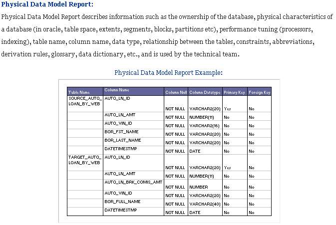
b. Physical data model report
3. Review data model with functional and technical team
4. Create SQL code from data model and co-ordinate with DBAs to create DB
5. Check to see data models and databases are in synch
6. Maintain change log for each data model
Star and Snowflake schemas
- Star and snowflake schemas are most commonly found in dimensional data warehouses and data marts where speed of data retrieval is more important than the efficiency of data manipulations. As such, the tables in these schemas are not normalized much, and are frequently designed at a level of normalization short of third normal form.
- Deciding whether to employ a star schema or a snowflake schema should involve considering the relative strengths of the database platform in question and the query tool to be employed.
- Star schemas should be favored with query tools that largely expose users to the underlying table structures, and in environments where most queries are simpler in nature.
- Snowflake schemas are often better with more sophisticated query tools that create a layer of abstraction between the users and raw table structures for environments having numerous queries with complex criteria.
Star schema
- Star schema classifies the attributes of an event into facts(measured numeric/time data), and descriptive dimension attributes (product id, customer name, sale date) that give the facts a context. A fact record is the nexus between the specific dimension values and the recorded facts. The Facts are grouped together by grain (level of detail) and stored in the fact table. Dimension attributes are organized into affinity groups and stored a minimal number of dimension tables.
- They are designed to optimize user ease-of-use and retrieval performance by minimizing the number of tables to join to materialize a transaction.
- It is called such as it resembles a constellation of stars, generally several bright stars (facts) surrounded by dimmer ones (dimensions).
- Fact table holds the metric values recorded for a specific event. Because of the desire to hold atomic level data, there generally are a very large number of records(billions). Special care is taken to minimize the number and size of attributes in order to constrain the overall table size and maintain performance. Fact tables generally come in 3 flavors - transaction (facts about a specific event eg Sale), snapshot (facts recorded at a point in time (eg Account details at month end ), and accumulating snapshot tables (eg month-to-date sales for a product).
- Dimension tables, usually have few records compared to fact tables, but may have a very large number of attributes that describe the fact data.
Benefits of Star schema
- The primary benefit of star schema is its simplicity for users to write, and databases to process: queries are written with simple inner joins between the facts and a small number of dimensions. Star joins are simpler than possible in snowflake schema. Where conditions need only to filter on the attributes desired, and aggregations are fast.
- Star schema is a way to implement multidimensional database (MDDB) functionality using a mainstream relational database: given most organizations' commitment to relational databases, a specialized multidimensional DBMS is likely to be both expensive and inconvenient.
Snowflake schema
- The snowflake schema is similar to the star schema. However, in the snowflake schema, dimensions are normalized into multiple related tables, whereas the star schema's dimensions are normalized with each dimension represented by a single table.
- A complex snowflake shape emerges when the dimensions of a snowflake schema are elaborate, having multiple levels of relationships, and the child tables have multiple parent tables ("forks in the road"). The "snowflaking" effect only affects the dimension tables and NOT the fact tables.
Benefits of snowflake schema
- Some OLAP multidimensional database modeling tools that use dimensional data marts as data sources are optimized for snowflake schemas.
- If a dimension is very sparse (i.e. most of the possible values for the dimension have no data) and/or a dimension has a very long list of attributes which may be used in a query, the dimension table may occupy a significant proportion of the database and snowflaking may be appropriate.
- A multidimensional view is sometimes added to an existing transactional database to aid reporting. In this case, the tables which describe the dimensions will already exist and will typically be normalized. A snowflake schema will therefore be easier to implement.
- Snowflake schema can sometimes reflect the way in which users think about data. Users may prefer to generate queries using a star schema in some cases, although this may or may not be reflected in the underlying organization of the database.
- Some users may wish to submit queries to the database which, using conventional multidimensional reporting tools, cannot be expressed within a simple star schema. This is particularly common in data mining of customer databases, where a common requirement is to locate common factors between customers who bought products meeting complex criteria. Some snowflaking would typically be required to permit simple query tools to form such a query, especially if provision for these forms of query weren't anticipated when the data warehouse was first designed.
Fact Table
- A fact table is the primary table in a dimensional model where the numerical performance measurements of the business are stored.
- A row in a fact table corresponds to a measurement. A measurement is a row in a fact table. All the measurements in a fact table must be at the same grain.
- We use the term fact to represent a business measure.
- A measurement is taken at the intersection of all the dimensions (day, product, & store). This list of dimensions defines the grain of the fact table & tells us what the scope of the measurement is.
- The most useful facts in a fact table are numeric & additive.
- Fact tables express the many-to-many relationships between dimensions in dimensional models.
- Ex: sales amount would be such a measure. This measure is stored in the fact table with the appropriate granularity. Ex: It can be sales amount by store by day. In this case, the fact table would contain three columns: A date column, a store column, & a sales amount column.
Dimensional Table
- Dimension tables are integral companions to a fact table. The dimension tables contain the textual descriptors of the business.
- Each dimension is defined by its single primary key, which serves as the basis for referential integrity with any given fact table to which it is joined
- Dimension attributes serve as the primary source of query constraints, groupings, & report labels. In a query or report request, attributes are identified as the by words. Ex: when a user states that he or she wants to see dollar sales by week by brand, week & brand must be available as dimension attributes. The power of the DW is directly proportional to the quality & depth of the dimension attributes.
- Dimension tables are the entry points into the fact table. Robust dimension attributes deliver robust analytic slicing & dicing capabilities. The dimensions implement the user interface to the DW. The best attributes are textual & discrete.
- Note
- Sometimes when we are designing a database it is unclear whether a numeric data field extracted from a production data source is a fact or dimension attribute. We often can make the decision by asking whether the field is a measurement that takes on lots of values & participates in calculations (making it a fact) or is a discretely valued description that is more or less constant & participates in constraints (making it a dimensional attribute).
- Ex: The standard cost for a product seems like a constant attribute of the product but may be changed so often that eventually we decide that it is more like a measured fact. Occasionally, we can’t be certain of the classification. In such cases, it may be possible to model the data field either way, as a matter of designer’s prerogative.
Lookup Table
- The lookup table provides the detailed information about the attributes.
- Ex: the lookup table for the Quarter attribute would include a list of all of the quarters available in the DW. Each row (each quarter) may have several fields, one for the unique ID that identifies the quarter, & one or more additional fields that specifies how that particular quarter is represented on a report (Ex: 1st Quarter of 2001 may be represented as Q1 2001 / 2001 Q1).
- A dimensional model includes fact tables & lookup tables. Fact tables connect to one or more lookup tables, but fact tables do not have direct relationships to one another. Dimensions & hierarchies are represented by lookup tables. Attributes are the non-key columns in the lookup tables.
Hierarchy
- A logical structure that uses ordered levels as a means of organizing data.
- A hierarchy can be used to define data aggregation; for example, in a time dimension, a hierarchy might be used to aggregate data from the Month level to the Quarter level, from the Quarter level to the Year level.
- A hierarchy can also be used to define a navigational drill path, regardless of whether the levels in the hierarchy represent aggregated totals or not.
Level
A
position in a hierarchy. For example, a time dimension might have a
hierarchy that represents data at the Month, Quarter, & Year
levels.


UML profile for Modeling
Agile approach is considered to requirements modeling. The high-level requirements are:
Need to support different types of models
Conceptual, logical, and physical data models
Need to support different types of data storage mechanisms (e.g. relational, object, XML, …)
Need to model entities and tables
Entities appear on logical and conceptual data models
Tables appear on physical data models for RDBs
Users/programs may have different levels of access to a table, including none, read-only, update, insert, and delete.
Need to model the attributes and columns
The type of the attribute/column
Need to support derived data
Different databases have different possible types
Some types have sizes (e.g CHAR) whereas with others the size is implied (e.g. Double)
Tables have one or more columns
Entities have one or more attributes
System columns are only accessible by the system itself
Data columns are accessible to any user/program granted rights to access the column
Users/programs may have different types of access to a column, including read and update access
Need to model relationships
Referential integrity rules
Identifying relationships
Non-identifying relationships
Inheritance
Aggregation
Composition
Need to model keys
Candidate keys
Primary keys
Alternate/secondary keys
Foreign keys
A table has zero or one primary key
A table has zero or more secondary keys
A table must have a primary key to have a secondary key
A key is composed of one or more columns
A key composed of two or more columns is called a composite key (terminology issue)
Any given column may be a part of zero or more keys
Associations between tables are implemented as foreign keys
Any
given column could be part of different types of keys (e.g. Column A is
part of the primary key for a table and the foreign key to another
table)
Logical models indicate candidate keys
Physical models indicate primary and alternate keys
Some keys may be natural (e.g. Invoice Number) whereas others are surrogate (e.g. a persistent object identifier (POID) )
Need to model constraints and behaviors
Triggers
Need to model stored procedures
Stored procedures can access data stored in zero or more tables
Access control rules
Need to model source of record/access
Indicate that a column/table/db is the, or at least one of, the official source of record
Indicate that a database element has been deprecated
Indicate the suggested database element which replaces a deprecated element
Indicate that a column/table/db is a copy of another
|
No comments:
Post a Comment
Note: Only a member of this blog may post a comment.